I/O
The Trigger I/O and I/O 1-6 panes are used to configure the camera's various signal inputs and outputs.

Expanded view of a single I/O port
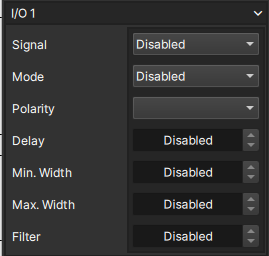
Signal
Used to assign a particular signal from the below table to the input or output port.
| Signal | Function |
|---|---|
| Event 1 1 | Used to tag events within the frame metadata |
| Event 2 1 | Used to tag events within the frame metadata |
| Frame Sync | Used to synchronize external devices to the camera's frame clock or vice versa |
| IRIG | Used to synchronize timecodes with an IRIG signal from another device or vice versa |
| Ready | Represents when camera is recording but not yet triggered (active for pre-trigger recording only) |
| Record | Represents when camera is recording (active for both pre and post-trigger recording) |
| Shutter | Represents camera's exposure time |
| Trigger | Used to trigger camera's frame buffer and stop the recording, dependent on the frame buffer's trigger offset |
For the dedicated Trigger I/O pane, the Signals field will only show two options -- Enabled or Disabled.
Mode
Configure the I/O directionality and circuit configuration mode
| Mode | Description |
|---|---|
| Disabled | I/O is disabled |
| Input | External device drives the input signal low or high |
| Input w/ Pull-Up | External device drives the input signal low or high-impedance (with internal pull-up resistor enabled) |
| Output (Push-Pull) | Camera drives the output signal low or high |
| Open-Drain Output | Camera drives the output signal low or high-impedance (with internal pull-up resistor enabled) |
| Open-Drain Bidirectional | Camera or external device drives the input/output signal low or high-impedance (with internal pull-up resistor enabled) |
Polarity
For the Frame Sync and Trigger signals, this setting determines if the camera reacts to the rising or falling edge of the signal. For all other signals (except IRIG), this settings determines if the signal is active in the high (i.e. +5 VDC) state or the low (i.e. 0 VDC) state.
| Polarity | Function |
|---|---|
| Active High | Signal will high when in the active state and low in the inactive state |
| Active Low | Signal will low when in the active state and high in the inactive state |
| Rising Edge | Camera reacts to the transition between low and high |
| Falling Edge | Camera reacts to the transition between high and low |
Pulse Manipluations
Allows users to modify signal characteristics to conform to the requirements and characteristics of external devices. The available manipulations are delay, minimum width, maximum width, and filter.
Right-clicking on the pulse manipulation text fields allows the unit to be changed by selecting the corresponding radio button. Alternatively, typing a new value with a different unit can also be used to change units.
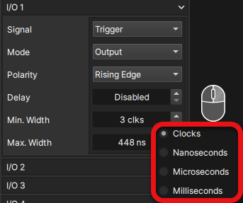
Delay
Specifies a signal delay in clock cycles 2, milliseconds, microseconds, or nanoseconds.
| I/O Mode | |
|---|---|
| Input Modes | Sets the delay time between when the signal is received from an external source, and when it is processed by the camera |
| Output Modes | Sets the delay time between when the signal is generated from the camera, and when it is output to external devices |
Min. Width
Specifies a minimum signal pulse width in clock cycles 2, milliseconds, microseconds, or nanoseconds.
| I/O Mode | |
|---|---|
| Input Modes | Sets the minimum pulse width that the input signal must be to be accepted. Shorter length signals are ignored |
| Output Modes | Stretches output pulses to be at least the desired minimum pulse width or longer |
Max. Width
Specifies a maximum signal pulse width in clock cycles 2, milliseconds, microseconds, or nanoseconds.
| I/O Mode | |
|---|---|
| Input Modes | Sets the maximum pulse width that the input signal can be to be accepted. Longer length signals are ignored |
| Output Modes | Truncates output pulses to be the desired maximum pulse width or shorter |
Frame sync output pulse width is 250ns by default
Filter
Low-pass filter that instructs the camera to ignore the signal if it occurs more frequently than the value of this setting.
e.g. - if the filter is set to 500Hz, then a 1000Hz signal will only register as 500Hz