Trigger
E9 cameras include a dedicated Trigger I/O. The trigger signal is used to stop the recording of a Take after the specified number of trigger offset frames. It functions the same as the Trigger button within the SLOW software, but allows for maximum precision and is recommended for applications that demand precise timing.
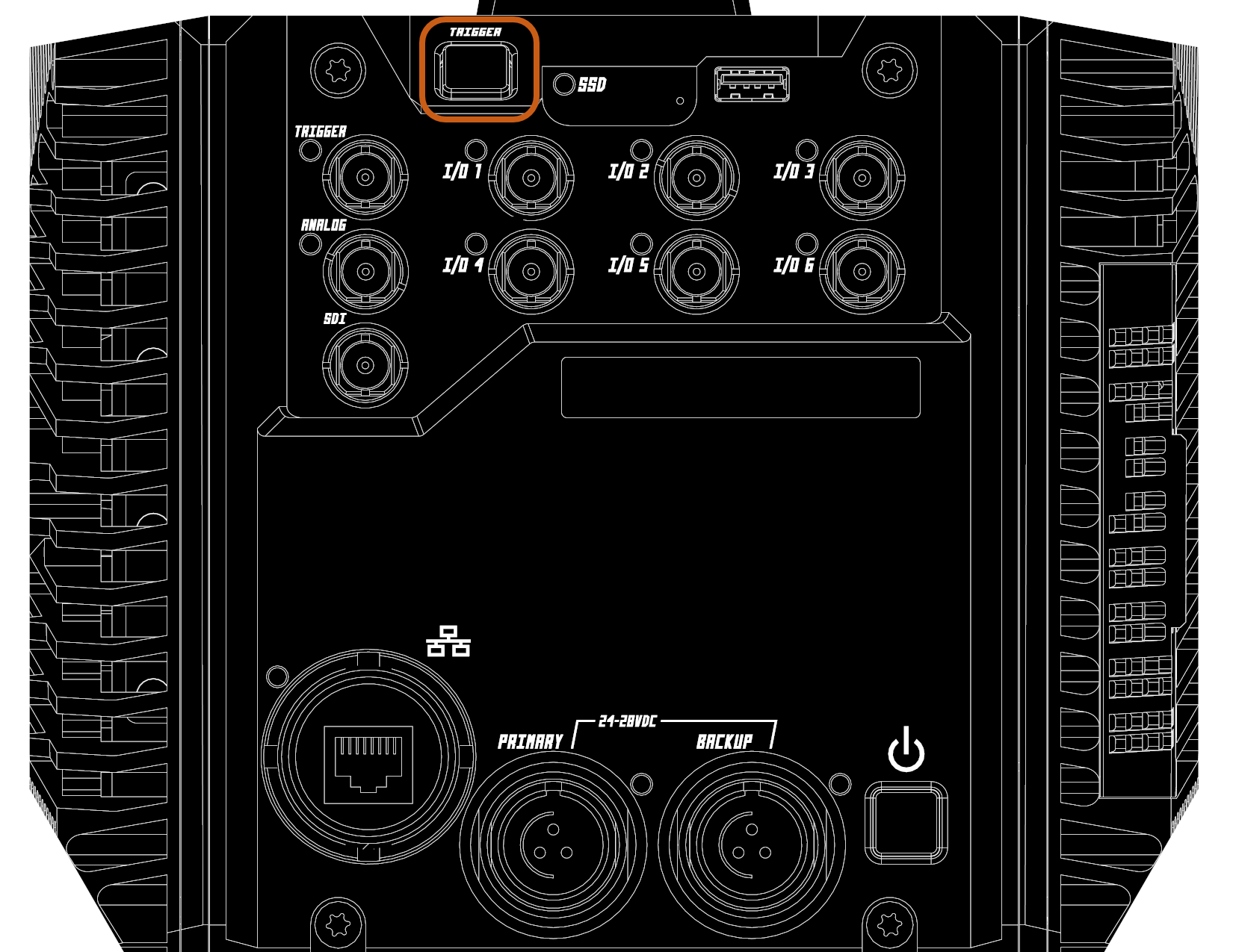
Location
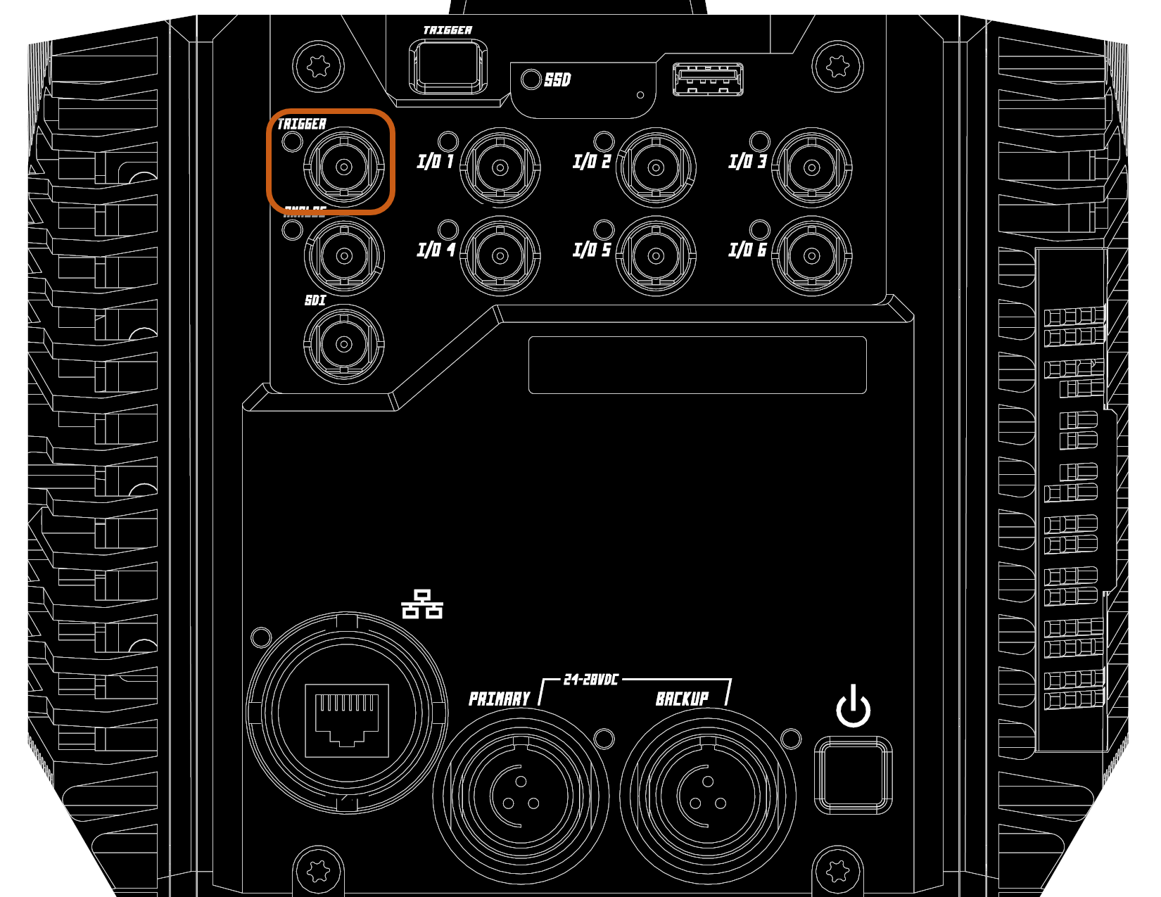
Connector
BNC (50-ohm)
Logic Levels

When configured as an input, the dedicated trigger I/O is compatible with 5V TTL, 5V CMOS, and 3.3V LVTTL external signals. It is also capable of receiving high-voltage triggers up to 28V.
As an output, the dedicated trigger output logic levels are compatible with 5V TTL and 5V CMOS external devices.
The maximum input voltage should not exceed 28VDC
I/O Configuration
See: SLOW Software > Camera Control > I/O
LED
The Trigger LED indicates the recording state of the frame buffer.
| LED State | Description |
|---|---|
| OFF | Camera is in standby; Not recording to frame buffer |
| Solid Red | Take is recording pre-trigger frames into the frame buffer partition |
| Blinkling Red | Take is triggered & recording post-trigger frames into the frame buffer partition |
Button
The trigger button functions the same as the Trigger button within the SLOW software or the Trigger I/O port in a falling-edge switch closure configuration.